
Description
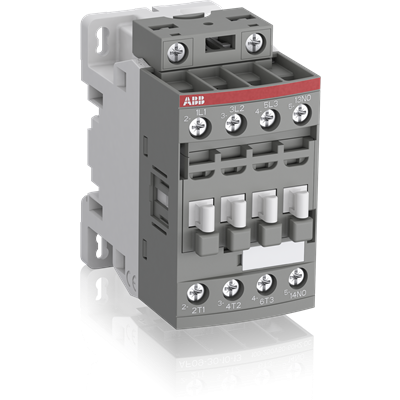
AF16-30-10-12 Block Contactor
The AF16-30-10-12 is a 3 pole – 690 V IEC or 600 UL contactor with 1 built-in auxiliary contact and screw terminals, controlling motors up to 7.5 kW / 400 V AC (AC-3) or 10 hp / 480 V UL and switching power circuits up to 30 A (AC-1) or 30 A UL general use. Thanks to the AF technology, the contactor has a wide control voltage range (48-130 V 50/60 Hz and DC), managing large control voltage variations, reducing panel energy consumptions and ensuring distinct operations in unstable networks. Furthermore, surge protection is built-in, offering a compact solution. AF contactors have a block type design, can be easily extended with add-on auxiliary contact blocks and an additional wide range of accessories.
Product Net Dimensions: Width: 4.5 cm, Depth: 7.7 cm, Height: 8.6 cm
Product Weight: 0.27 kg
Number of Poles: 3P
Main Contacts: 3 NO, 0 NC
Auxiliary Contacts: 1 NO, 0 NC
Rated Operational Voltage: Auxiliary Circuit: 690 V, Main Circuit: 690 V
Rated Frequency: 50 / 60 Hz for auxiliary, control and main circuits
Thermal Current (Ith): 35 A at 40 °C
Rated Operational Current AC-1: 30 A at 690 V (40 °C and 60 °C), 26 A at 690 V (70 °C)
Rated Operational Current AC-3: 18 A at 415 V and 440 V (60 °C), 15 A at 500 V (60 °C), 10.5 A at 690 V (60 °C)
Rated Operational Current AC-15: 2 A at 500 V and 690 V, 6 A at 24 / 127 V, 4 A at 220 / 240 V, 3 A at 400 / 440 V
Rated Operational Current DC-1: up to 30 A at 110 V depending on poles in series and temperature
Rated Operational Power AC-3: 7.5 kW at 400 V, 9 kW at 415 V, 440 V, 500 V and 690 V, 4 kW at 220 / 230 / 240 V
Short-time Withstand Current Low Voltage: 150 A for 10 s at 40 °C ambient temperature, in free air, from a cold state
Max Breaking Capacity: 250 A at 440 V, 106 A at 690 V
Rated Insulation Voltage (Ui): 690 V acc. to IEC 60947-4-1 and IEC 60947-5-1, 600 V acc. to UL/CSA
Rated Impulse Withstand Voltage (Uimp): 6 kV
Maximum Electrical Switching Frequency: Up to 1200 cycles per hour depending on AC or DC utilization category
Maximum Mechanical Switching Frequency: 3600 cycles per hour
Control Circuit Voltage (Uc): 48 to 130 V for 50 Hz, 60 Hz and DC operation
Power Loss: 0.1 W at 6 A per pole, 1.2 W at rated AC-1 conditions per pole, 0.35 W at rated AC-3 conditions per pole
Operate Times: Between coil de-energization and NC contact closing: 13 to 98 ms; Between coil energization and NO contact closing: 40 to 95 ms
Mounting: TH35-15 (35 x 15 mm) mounting rail acc. to IEC 60715; 2 x M4 screws placed diagonally
Connecting Capacity Main Circuit: Flexible with ferrule: 0.75 to 6 mm²; Rigid solid: 1 to 4 mm²
Degree of Protection: IP20 for auxiliary, coil, and main terminals acc. to IEC 60529 and IEC 60947-1
Tightening Torque: Auxiliary and control circuits 1.2 N·m; Main circuit 1.5 N·m
Terminal Type: Screw Terminals
UL/CSA Ratings: Maximum operating voltage 600 V; General use rating 30 A at 600 V AC; Horsepower ratings from 1.5 hp (120 V AC single phase) up to 15 hp (550-600 V AC three phase)
Environmental: Ambient air temperature range: -25 to 60 °C (with thermal overload relay), -40 to 70 °C (without relay), storage: -60 to 80 °C; Climatic withstand category B acc. to IEC 60947-1 Annex Q
Operating Altitude: Up to 3000 m without derating
Resistance to Shock: Up to 30 g depending on direction and open/closed state
Pollution Degree: 3
Sustainable Material Content: Packaging contains 86% recycled cardboard; product contains 28% recycled metal