Description
Product Name
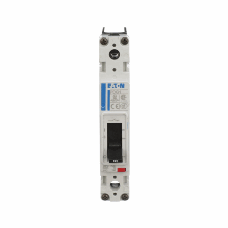
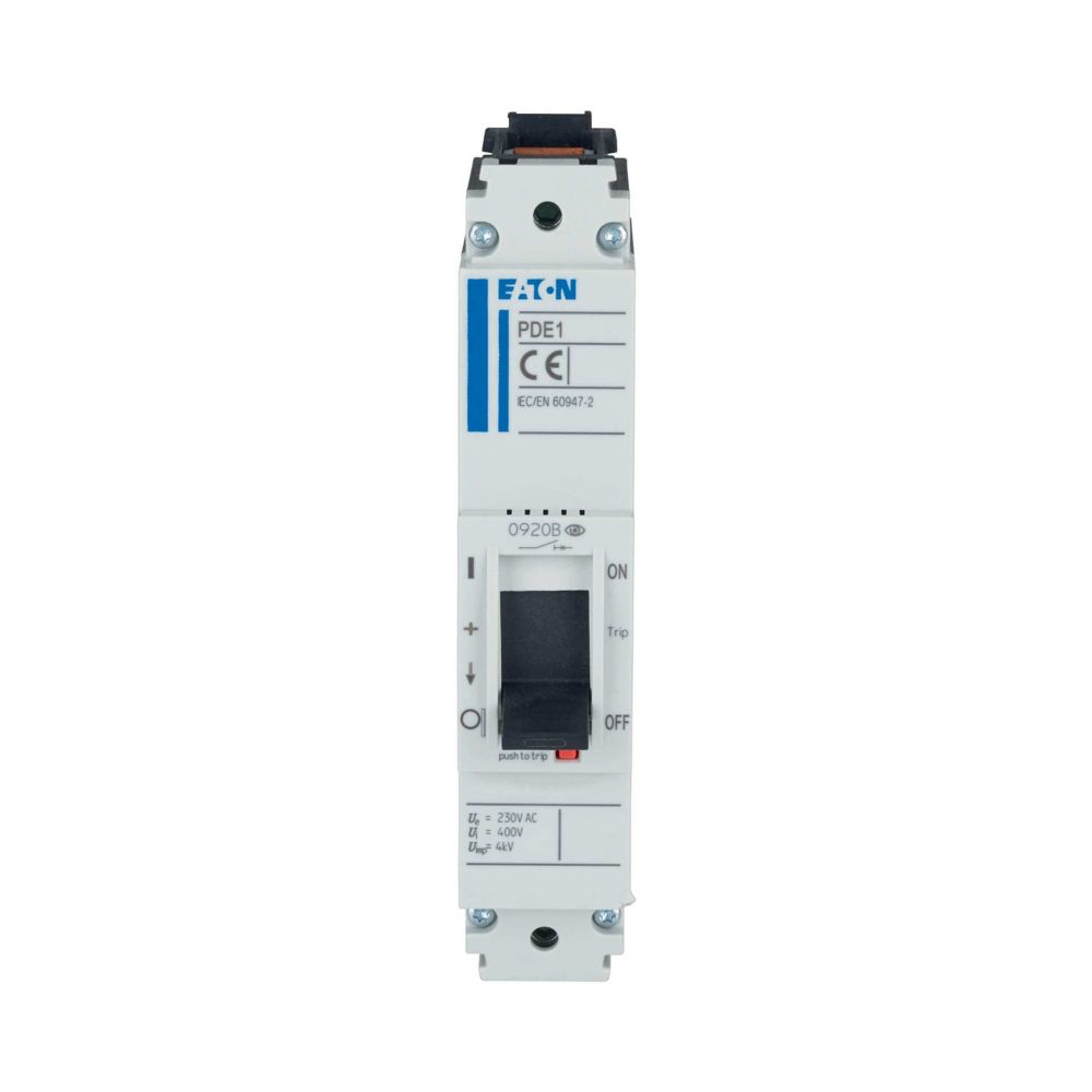
Eaton Moeller series Power Defense molded case circuit-breaker
Description
Eaton Moeller series Power Defense – Molded Case Circuit Breaker. Circuit breaker, 50A, 25kA, 1p, box terminal
General Specifications
Catalog Number: PDE11F0050TFFJ
Model Code: PDE11F0050TFFJ
EAN: 9010238099333
Product Length/Depth: 8.8 cm
Product Height: 14.5 cm
Product Width: 3 cm
Product Weight: 0.386 kg
Compliances: RoHS conform
Certifications: IEC IEC/EN 60947
Delivery Program
Type: Circuit breaker
Circuit breaker frame type: PDE1
Number of poles: Single-pole
Amperage Rating: 50 A
Release system: Thermomagnetic release
Features: Protection unit
Special features: Fixed overload releases Ir
Technical Data – Electrical
Voltage rating: 230 V – 230 V
Rated impulse withstand voltage (Uimp) at auxiliary contacts: 6000 V
Rated impulse withstand voltage (Uimp) at main contacts: 6000 V
Rated current (Iu): 50 A
Instantaneous current setting (Ii) – min: 500 A
Instantaneous current setting (Ii) – max: 500 A
Overload current setting (Ir) – min: 40 A
Overload current setting (Ir) – max: 50 A
Rated short-circuit breaking capacity Ics (IEC/EN 60947) at 400/415 V, 50/60 Hz: 18 kA
Short-circuit total breaktime: < 10 ms
Electrical connection type of main circuit: Frame clamp
Isolation: 500 V AC (between auxiliary contacts and main contacts) 300 V AC (between the auxiliary contacts)
Number of operations per hour – max: 120
Handle type: Rocker lever
Utilization category: A
Overvoltage category: III
Pollution degree: 3
Direction of incoming supply: Vertical and 90° in all directions
Technical Data – Mechanical
Mounting Method: Complete device in housing DIN rail (top hat rail) mounting optional Fixed
Degree of protection: IP2X IP20 (basic degree of protection, in the operating controls area)
Degree of protection (IP), front side: IP40 (with insulating surround) IP66 (with door coupling rotary handle)
Degree of protection (terminations): IP10 (tunnel terminal) IP00 (terminations, phase isolator and band terminal)
Shock resistance: 20 g (half-sinusoidal shock 20 ms)
Number of auxiliary contacts (change-over contacts): 0
Number of auxiliary contacts (normally closed contacts): 0
Number of auxiliary contacts (normally open contacts): 0
Position of connection for main current circuit: Front side
Climatic proofing: Damp heat, constant, to IEC 60068-2-78 Damp heat, cyclic, to IEC 60068-2-30
Special features: Fixed overload releases Ir
Lifespan, mechanical: 20000 operations
Technical Data – Mechanical – Terminals
Standard terminals: Box terminal
Design Verification as per IEC/EN 61439 – Technical Data
Ambient operating temperature – min: -25 °C
Ambient operating temperature – max: 70 °C
Ambient storage temperature – min: -40 °C
Ambient storage temperature – max: 70 °C
Design Verification as per IEC/EN 61439
10.2.2 Corrosion resistance: Meets the product standard’s requirements.
10.2.3.1 Verification of thermal stability of enclosures: Meets the product standard’s requirements.
10.2.3.2 Verification of resistance of insulating materials to normal heat: Meets the product standard’s requirements.
10.2.3.3 Resistance of insulating materials to abnormal heat/fire by internal electrical effects: Meets the product standard’s requirements.
10.2.4 Resistance to ultra-violet (UV) radiation: Meets the product standard’s requirements.
10.2.5 Lifting: Does not apply, since the entire switchgear needs to be evaluated.
10.2.6 Mechanical impact: Does not apply, since the entire switchgear needs to be evaluated.
10.2.7 Inscriptions: Meets the product standard’s requirements.
10.3 Degree of protection of assemblies: Does not apply, since the entire switchgear needs to be evaluated.
10.4 Clearances and creepage distances: Meets the product standard’s requirements.
10.5 Protection against electric shock: Does not apply, since the entire switchgear needs to be evaluated.
10.6 Incorporation of switching devices and components: Does not apply, since the entire switchgear needs to be evaluated.
10.7 Internal electrical circuits and connections: Is the panel builder’s responsibility.
10.8 Connections for external conductors: Is the panel builder’s responsibility.
10.9.2 Power-frequency electric strength: Is the panel builder’s responsibility.
10.9.3 Impulse withstand voltage: Is the panel builder’s responsibility.
10.9.4 Testing of enclosures made of insulating material: Is the panel builder’s responsibility.
10.10 Temperature rise: The panel builder is responsible for the temperature rise calculation. Eaton will provide heat dissipation data for the devices.
10.11 Short-circuit rating: Is the panel builder’s responsibility. The specifications for the switchgear must be observed.
10.12 Electromagnetic compatibility: Is the panel builder’s responsibility. The specifications for the switchgear must be observed.
10.13 Mechanical function: The device meets the requirements, provided the information in the instruction leaflet (IL) is observed.
Additional Information
Functions: System and cable protection
Customs Tariff Code
85362000