Description
Product Name
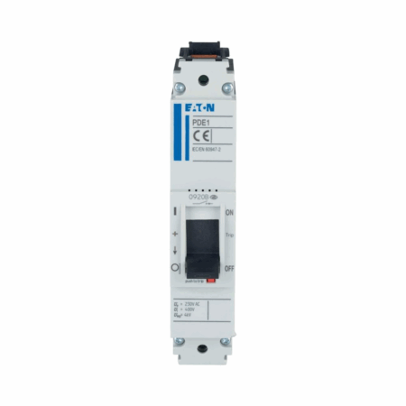
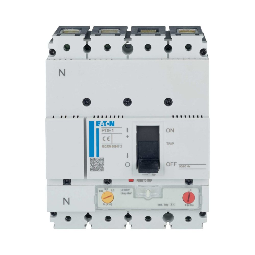
Eaton Moeller series Power Defense molded case circuit-breaker
Catalog Number
PDE14F0032VAAJ
Dimensions and Weight
Length/Depth: 14.6 cm
Height: 8.7 cm
Width: 12.0 cm
Weight: 1.325 kg
Electrical Ratings
Amperage Rating: 32 A
Voltage rating: 220 V – 440 V
Rated current (Iu): 32 A
Max. rated operation voltage Ue AC: 440 V
Voltage rating (DC): 250 V
Rated insulation voltage (Ui): 800 V AC
Performance
Rated short-circuit breaking capacity Ics at 230 V, 50/60 Hz: 35 kA
Rated short-circuit breaking capacity Ics at 400/415 V, 50/60 Hz: 25 kA
Rated short-circuit breaking capacity Ics at 440 V, 50/60 Hz: 15 kA
Power loss: 36.1 W
Instantaneous current setting (Ii) – max: 350 A
Instantaneous current setting (Ii) – min: 32 A
Overload current setting (Ir) – max: 32 A
Overload current setting (Ir) – min: 25.6 A
Number of operations per hour – max: 120
Features and Construction
Circuit breaker frame type: PDE1
Features: Protection unit; Motor drive optional
Special features: Thermally and magnetically adjustable (calibrated at 50 °C)
Release system: Thermomagnetic release
Handle type: Rocker lever
Functions: System and cable protection
Position of connection for main current circuit: Front side
Standard terminals: Box terminal
Electrical connection type of main circuit: Frame clamp
Number of poles: Four-pole
Environmental and Mechanical
Pollution degree: 3
Ambient operating temperature – max: 70 °C
Ambient operating temperature – min: -20 °C
Ambient storage temperature – max: 70 °C
Ambient storage temperature – min: -20 °C
Lifespan, mechanical: 25000 operations
Mounting Method: DIN rail (top hat rail) mounting optional, Fixed, Complete device in housing
Degree of protection: IP2X
Overvoltage category: III
Direction of incoming supply: Vertical and 90° in all directions
Compliance and Certification
Compliances: RoHS conform
Certifications: IEC IEC/EN 60947
Additional Information
Temperature rise: The panel builder is responsible for the temperature rise calculation. Eaton will provide heat dissipation data for the devices.
Short-circuit rating: Is the panel builder’s responsibility. The specifications for the switchgear must be observed.
Electromagnetic compatibility: Is the panel builder’s responsibility. The specifications for the switchgear must be observed.
Mechanical function: The device meets the requirements, provided the information in the instruction leaflet (IL) is observed.
Corrosion resistance, verification of thermal stability of enclosures, insulation material resistance to heat and fire, resistance to UV radiation, and inscriptions: Meets the product standard’s requirements.
Testing and protection aspects are mainly the panel builder’s responsibility or are not applicable since the entire switchgear needs to be evaluated.
Number of auxiliary contacts: 0 (change-over, normally closed, normally open)
Rated impulse withstand voltage (Uimp) at auxiliary and main contacts: 6000 V