Complete as per Water Authority (WAJ) and Miyahuna Specification in Jordan.
A. General Requirements
1. The starters shall be Auto Transformer type as required, suitable for a squirrel cage induction motor 400 Vac, 50 Hz, 3 phase. The starting steps shall be such that the maximum starting current does not exceed two and half times the motor rated current and tapping of 70%.
2. Each motor starter shall compromise the following:
a. Automatic molded case circuit breaker (MCCB) 50 kA rated short circuit breaking capacity (1.2 of rated capacity), NEMA CLASS 10,provided with adjustable thermal and magnetic trip points.
b. Starting, bridging, and running contractors as required.(AC3 CATEGORY).
c. Starting auto transformer with 70% tapping.
d. All protection and control relays for the pump sets as specified.
e. All alarm indication lamps for the pump set as specified.
f. Re-settable audible and visible alarm system for all faults.
g. Electronic overload relay as specified.
h. Delay on timer with range of 0.5 sec. to 10 sec.
3. The main, step, and star contactors shall be selected in accordance with utilization category AC3 at 400 Vac, (100%, 70%, 35% of rated power respectively).
4. The electronic overload protection relay, of a suitable adjustable range, shall be installed between the running contactor and motor, (with or without current transformer). The overload range shall be approximately from (80%) – (120%) of the nominal current rating of the motor.
5. The starting auto transformer shall be rated to stand a minimum of four starts per hour at an ambient temperature of 50ºC.
6. The motor starter shall incorporate the following protection instruments:
Adjustable SOLID STATE electronic overload protection.
Dry running protection relay with a sensitivity equals to or more than 100 Kilo Ohm.
One power monitor relay which shall trip in case of:
a-Incorrect phase sequence,
b-Over voltage,+10% of rated voltage.
c-Under voltage,-10% of rated voltage.
d-Phase failure,
Motor thermal protection relay, to protect the motor from over heating. Compatible with the sensor provided in the motor winding which must be PT100 ( three wire) and PTC resistor sensor as following:
a-digital indication.
b-adjustable from 0c to 100c,trip on 70c.
c-two change over contacts.
d-apply on 3-wire resistor sensor.
e-supply voltage 220v-230v,50 Hz.
Thermal protection relay with micro thermal Contact, to prohibit starting the motor when the Auto transformer is overheated, and to protect the Auto transformer.
7. Separate current transformers shall be provided for protection and instrumentation processes.The rated burden shall be as required by the instrument and/or protection device, but not less than 10VA.
8. Fuses and links shall be grouped where appropriate according to their functions and shall be clearly marked both on panels and the associated wiring diagrams.
9. Auto transformer shall have the following features:
a-Air cooled design
b-The core and coil shall be twice impregnated under vacuum in high temperature grade.
c-It shall be designed and tested to meet the requirements of IEC 292-4 for 50ºC ambient temperature.
d-Starts per hour 4 times, 10 sec. Each.
e-Phases: 3
f-Transformation ratio: 400/280 Volts, tapping: 70%.
g-PTC resistor sensor or Micro-thermal contact shall be inserted in the Auto-transformer winding, to protect it against overheating.
h-.Insulation class: F
10. The starter shall be fully assembled by the manufacturer, and where modifications such as additions of extra protection devices or indications are required, these modifications shall be performed in a similar manner by the original equipment manufactures. In such case full details of modifications and circuit diagrams shall be provided.
11. Each starter shall have its own dry running sensor (installed on the suction of its pump, i.e. each pump) and its own dry running relay inside the starter panel. This protection shall be independent from that low water level or dry running installed in the reservoir, which shall be connected in series with them as a protection.
12. All power circuits in the A.T.ST, shall be protected by molded case circuit breaker (MCCB) which has adjustable thermal, magnetic trip units and short circuit breaking capacity not less than 50 kA, unless otherwise specified elsewhere, and shall comply with IEC publications 157-1, 292, and 947. NEMA CLASS 10.
13. Control circuit in the A.T.ST. shall be protected by miniature circuit breakers (MCB) with current limiting feature, and I.C. not less than 6 kA according to IEC 157-1 P1, (or fuses if approved by WAJ).
14. Complete circuit diagrams shall be provided together with service instructions, and spare parts list for all components used in the starter panel, and they shall be supplied in a transparent plastic case inside a pocket on the backside of panel door.
15. The manufacturer should conduct the required tests on each starter as per IEC 439-1:1990, and the test should be witnessed by WAJ representative at the suppliers workshop/ or factory. The required tests are (but not limited to) the following:
a-Visual inspection.
b-Mechanical inspection.
c-Operation test.
d-H.V. test: 2.5 kV for 1 min.
e-Insulation (Megger) test.
f-Primary injection test.
g-Secondary injection test (for measuring instruments and protection).
16. The manufacturer shall submit test report (certificate) for each panel showing that the starters were completely tested, and setting of relays were adjusted.
17. All these protection device including the starter shall be labeled comprehensively for all wires, cables, devices, etc. with elastic rubber tireless and rigidly-fixed labeled terminal bars for the out going wires out of starters, all in approved execution of the Engineer & WAJ.
18. The supplier shall provide with his bid a detailed list(s) of all components (see please enclosure no. 1), whether major or minor, which shall be incorporated in his offer and in the starter. Failure to provide such list(s) shall result in the rejection of the bid.
19. The control relays should be one unit with appropriate NO, NC, the current should be not less than 10 Amp at 220 V and 4 Amp at 380 V, AC15, Ith not less than 20A, according to IEC 60947-4-1, 60947-5-1
shall be adequately braced to give a rigid structure. Adequate removable eye bolts for lifting purposes shall be provided.
3. Access to the cubicles compartment for all normal routine maintenance shall be from the front by hinged and lockable doors secured with cam type fasteners and cylinder locks with removable key. Hinges shall be of substantial size and stops shall be provided to prevent doors touching adjacent cubicles. Other access shall be by means of bolted panels. The maximum width of any door shall be 800 mm.
4. Protection category of starters’ enclosures shall be at least IP54 according to IEC publication 529-10/91.
5. All cables and piping shall be made through glands in a plate covering the base of the cubicles.
6. The base plate shall be of non magnetic material to avoid electric heating.
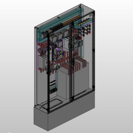
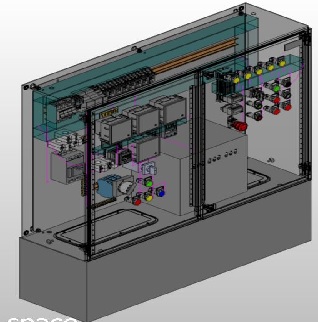
7. All the wiring, instruments, devices and all parts of the panel shall be facing the front of the panels, i.e. it shall not be needed to go to the rear of the panels to do anything to it, anytime (for dismantling, maintenance, reinstallation, etc.)
8. The auto transformer shall be fixed in a way that its longitudinal axis parallel to the rear plate of the panel.
9. Each starter panel shall enclose all related devices (i.e. equipment, contactors, relays, controls, etc.), no devices related to the starter shall be installed outside the starter enclosure, unless otherwise specified.
10. Unless otherwise mentioned elsewhere or approved by the engineer, the minimum facial width of the starter shall not be less than (60) cm, and the depth shall not be less than (30) cm. The height shall be approved initially by the Engineer according to the power rating of the starter.
11. Components shall be mounted in a way to prevent mechanical shocks transmitted from large components to small components and there by adversely affecting their proper functions. The components shall be so arranged to give adequate accessibility for maintenance and for removal of any one component with the minimum disturbance to the wiring. All bolts, nuts, screws, hinges, handles, etc., shall of galvanized or stainless steal, cadmium plated steel, or chrome-plated steel as appropriate.
12. The internal wring of all cubicles shall be completed before delivery.
13. Interlocks of a substantial mechanical type shall be provided in each cubicle between the door and the circuit breaker so that the door cannot be opened unless the circuit breaker is in the OFF position and all live parts, which can be accidentally touched, have been disconnected.
14. The design of each motor control switchboard shall also comply with the requirements of class 3 equipment of BS 5486 (clause N.2.1.3). The outline of this requirement is as follows:
Class 3: The whole busbars, including the conductor connecting the busbars to each outgoing unit shall be arranged to withstand a short circuit at any point.
15.The FBA shall be designed to withstand any external fault. In the event of any internal arcing fault on a functional unit, the damage should be confirmed to that unit so that the busbars and all other functional units remain fit for further service. However, the conductors connecting the busbars to the outgoing unit might be damaged by the internal arcing fault.
16. Starter’s contractors interconnections (wiring):
The maximum ampere loading for the power inter-connectors between main, step, and star contactors shall not be rated more than (2.5) amp/mm2, (the bigger cable or busbar cross section shall be installed in case the computed cross section is not available).
17. All the input inter-connectors for the main, step (bridging) and star contactors in starters of power (200) kW and above shall e insulated copper busbars.
18. For starters of power less than (200) kW, the input and output inter-connectors for the contactors (main, step and star) shall be PVC insulated Cu cables.
19. Every starter panel with height less than 1600 mm shall have an empty metal base covered from the sides for a height not less than 30 cm in which nothing shall be installed. There must be left additional 30 cm over that base to install any connection bar or terminal L bar for cables to the panel C.B. and for the outgoing cables to the motor.
20. Operation of main, step and short (star)contactors should be in away such that the step contactor is OFF, delayed extra 2 second than the set starting time , such that the main contactor is totally powered
For free standing enclosures with height 1800 mm and above, a 100 mm steel plinth shall be installed.
C. Controls, Indication & Alarms:
1. The operating push buttons, switches, or handles of all circuit breakers, motor starters, isolators, etc. shall be located on the doors of the cubicles, and there shall be visual indications of the “ON” and “OFF” positions.
2. All operations of fault and alarm circuits shall be clearly and individually indicated on the front of the switchboard by lamp operation.
3. Fault and alarm indication lamps shall remain ON until the cause has been cleared and the system has been manually reset.
4. The front of the starter panels shall contain the following signaling, controls and instruments:
a-A set of “ON” and “OFF” push buttons.
b-One voltmeter 0-500VAC with selector switch to monitor the 3 phases + neutral voltages.
c-Three ammeters “one per phase” with double scale.
d-One running hours recorder without resetting facility to record up to 9999 hours.
e-Indication lamps to show the following:
Motor “ON” and “OFF” and “FAULT”.
The motor is overloaded.
Low water level trip.
Motor winding high temperature trip.
Auto transformers winding high temperature trip.
R-S-T indication lamps (for A.T.ST. 350 kW and above).
f-One operating pulses recorder or meter (digital type) for starts count.
g-One stay-put push button for emergency stopping.
h-One audible alarm Re-settable buzzer for all faults.
5.Indication lamps and push buttons shall be colored as follows:
Indicating Lamp
Color ON Green
OFF Red
Fault Red
AlarmsYellow
Heaters Blue
Push Buttons Color
Start Green
Stop Red
Alarm Accept Black or White
Emergency Stop Red
Horn Silencer Yellow
6. Each indicating lamp shall be of illuminated push-button type, in order to incorporate a push-to-test feature (centralized lamp test is not accepted).
7. For the purpose of remote indication, voltage free contact shall be provided to duplicate the ON, OFF and fault indications. The contacts shall be wired to outgoing terminals and shall be rated for 2 Amps at 24 volts DC.
Option
The bidder shall Starter shall integrates various motor control architectures with various types of communication. and it comprises all components required to build a complete motor control application from SCADA system to starter devices.
- Display 20 Products per page